


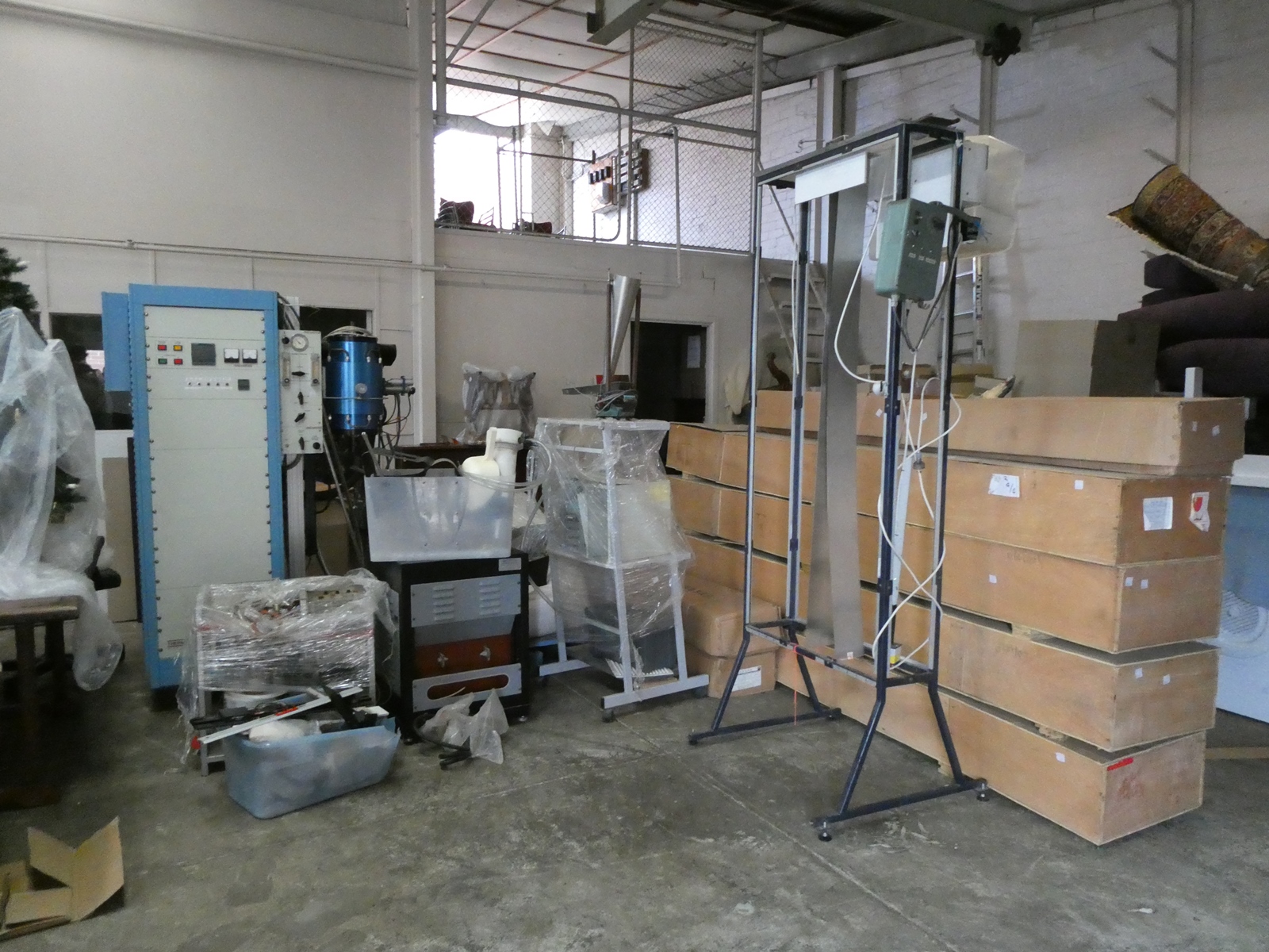


2500 degree Celsius High Temperature Industrial Furnace
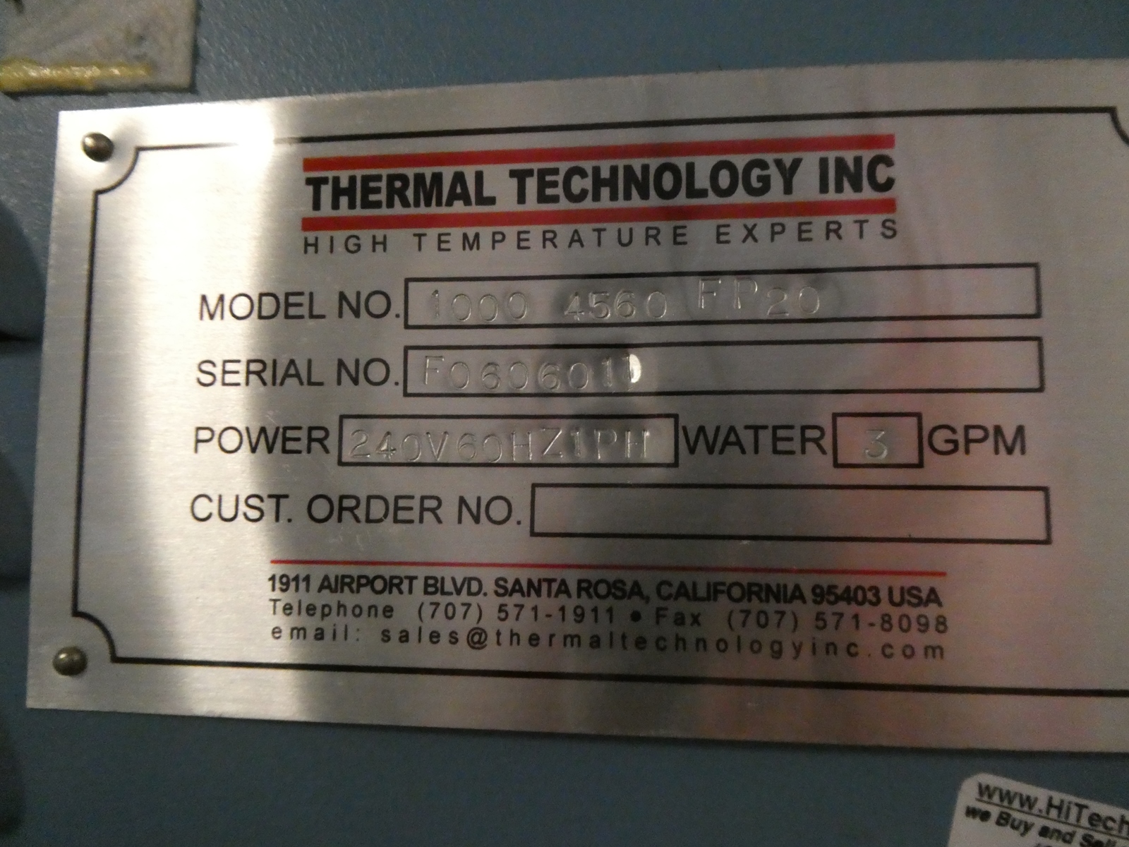
Thermal Technologies Model 1000-4560-FP30, which is rated to 2500 degrees celsius. This high temperature Industrial Furnace has a working volume of 4 inches diameter by 6 inches high and has done only 100 hours of operation.
Further specification information is as follows. For further information or to request an inspection, please contact Tom on 0488 020 101.
THERMAL TECHNOLOGY’S very high temperature furnaces are suitable for a wide variety of laboratory and small scale production applications requiring temperatures to 3000° C. They are versatile, simple to use, easy to install and reliable.
Work Zone Temp Model
(inches) Rating (°C) Number
2 dia. x 6 2800 1000-2560-FP20
3 dia. x 6 2650 1000-3560-FP20
4 dia. x 6 2500 1000-4560-FP30
4 dia. x 12 2000 1000-45120-FP30
6 dia. x 8 2300 1000-6580-FP40
8 dia. x 16 2300 HTG-9020-FP23
FEATURES
This specification is for a single zone, high temperature furnace that is capable of operation in dry inert, reducing and vacuum atmospheres. The basic Model 1000 system includes the graphite furnace, support column and bracket, power supply and water-cooled flexible power leads. The operational specifications for these systems are as follows:
HOT ZONE
High-density graphite resistance element.
ISULATION (Thermal)
High-purity graphite felt retained by a solid-wall graphite tube.
FURNACE CONSTRUCTION
Based on model, the furnace shell is either heavy-wall, seamless extruded 6061 T6 aluminium with an anodized interior and exterior or stainless steel (water-jacketed). The bulkheads are hard-anodized aluminium or nickel-plated copper (based on model) and the doors are nickel-plated copper. The shell and bulkheads have integral water-cooling passages. External surface temperatures are maintained at 65°C or less. O-ring seals are Viton.
The furnace has four 1 ⅛” – 16 radial and two axial threaded ports. One radial port is equipped with a 16mm (.62”) diameter viewing port with an anti-fog gas diffuser. All other ports are plugged but will accept the addition of optional sight windows, thermocouples, pyrometers, feedthroughs, and valved adapters.
Power connections are at one end of the furnace through radially mounted, water-cooled copper feedthroughs, providing unimpeded access to the bulkheads and doors. Electrical connection between the feedthroughs and the element is made by simple internal clamp connections.
The hot zone has straight-through access for convenient loading from either end. Sight hearths in both ends of the furnace serve as thermal baffles and in the vertical position will support the work. A graphite tray is optionally available for attachment to either hearth to support work with the furnace in a horizontal position.
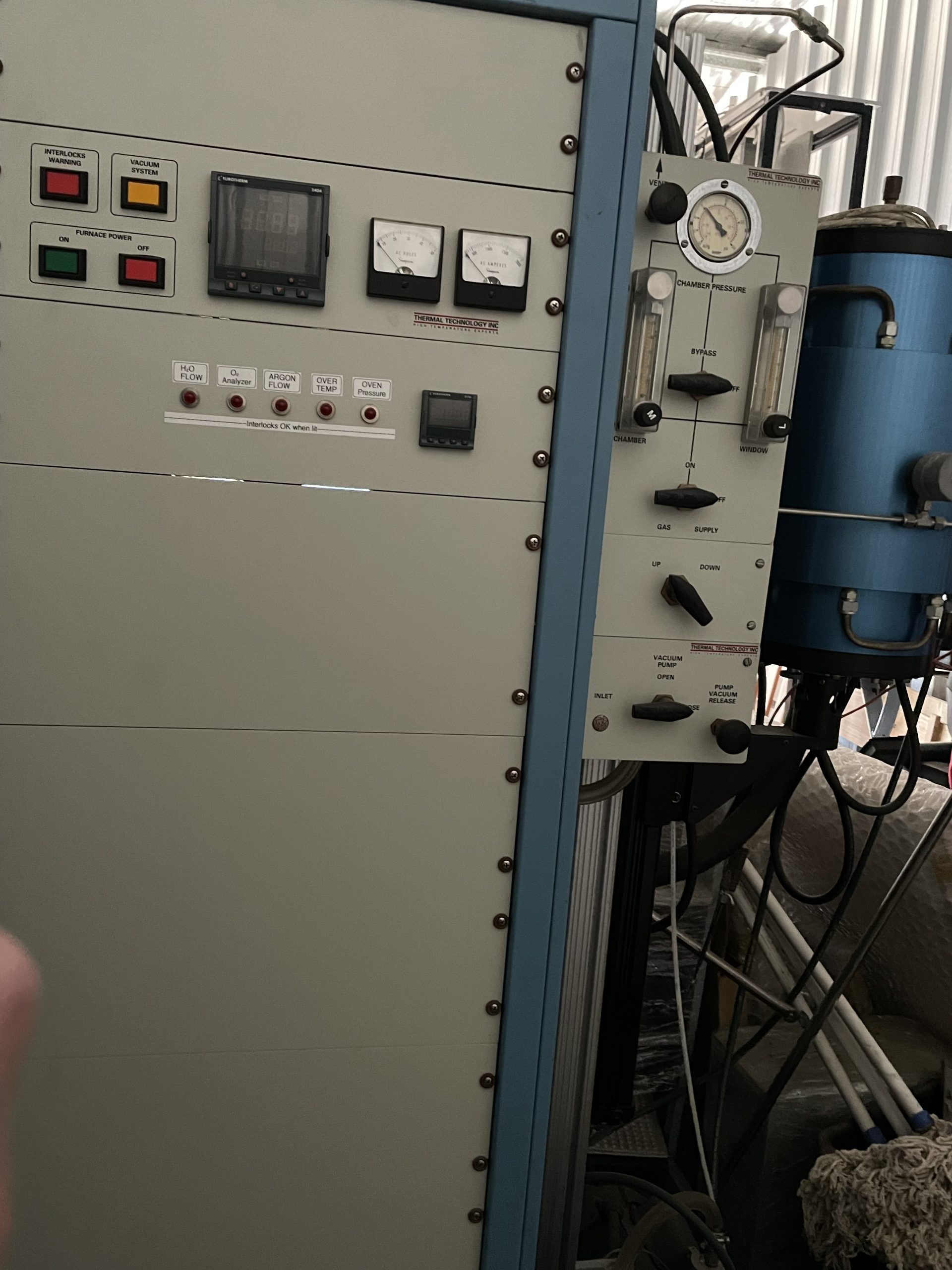
OPERATING ATMOSPHERES
Operating environments are inert or optional dry reducing atmospheres with pressure capabilities to 15 psig positive (103 kPa) and full vacuum. Operating vacuums in the 10-3 torr range (0.13 Pa) at temperatures to 2000°C and in the 10-1 torr range (13 Pa) at 2300°C can be achieved.
The addition of optional muffle tub assemblies permits working in oxidizing or wet reducing atmospheres compatible with aluminium oxide. Temperatures to 1800° C can be maintained with the furnace in the vertical position and to 1600°C in the horizontal position.
MAXIMUM TEMPERATURE
Temperatures up to 3000°C may be achieved dependent upon the furnace model. All maximum temperatures listed can be maintained in ultra-high purity helium gas under ideal conditions. Typically, a furnace should be selected having a maximum temperature rating 200°C higher than will be required for the maximum sustained operating temperature. This allows for heating element aging and other factors. Heating element life will be shortened at operating temperatures exceeding 2750°C.
TEMPERATURE UNIFORMITY
At 1750°C a 2-inch (50mm) long uniform temperature zone with a uniformity tolerance of ±3°C is possible in all models. A uniformity tolerance of ± 8°C is possible over 4 inches (100 mm). Uniformities will improve above 2000°C due to the high thermal radiation flux. Full length, very uniform hot zones can be provided for specific operating conditions upon special order.
TEMPERATURE AND OPERATING ATMOSPHERE
Argon or helium is satisfactory as inert operating gases. Since helium is a better thermal conductor than argon or nitrogen, greater heat losses will occur when using helium. This means that more power must be used with helium to achieve a given temperature than with argon or nitrogen. Argon should not be used above 2100°C because of its potential to ionize and sometimes ionization can start as low as 1700°C. The use of dry nitrogen as an inert gas is generally acceptable to 1700°C, when properly vented; nitrogen may be used to 2500°C. The furnace is compatible with dry reducing gases to 2500°C. The use of dry hydrogen is acceptable up to 2250°C (recommend combustible gas control and safety system).
CYCLE TIME
Heat-up time from ambient to maximum temperature is usually 30 minutes or less. Power-off cooling time from maximum to 100°C is 2 to 3 hours. More rapid cooling can be achieved by increasing gas flow into the furnace chamber or adding the optional cooling chamber accessory.
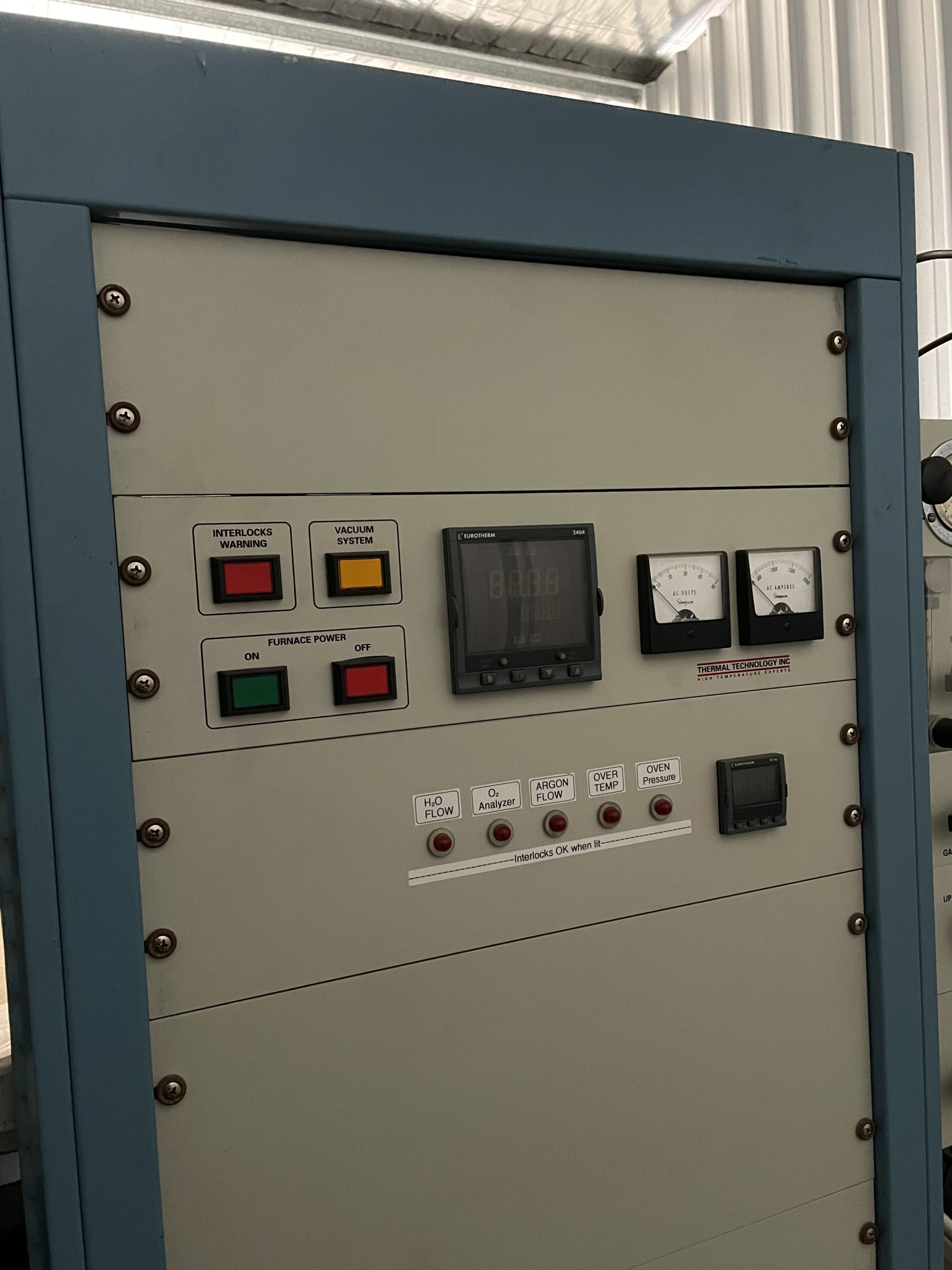
POWER SUPPLY
The power supply consists of an SCR power regulator and step-down load transformer.
Power is activated with an ON/OFF switch that controls a furnace power contactor. A panel meter indicates secondary voltage and current. A safety interlock with warning lamp, audible alarm, and OPERATE/RESET switch monitors cooling water flow and optional alarm circuits.
Power is manually adjustable from 0-100% by means of programmable controller (manual mode). Power supply components are housed in a floor console that shares a common 25” by 44” base with the furnace support column.
AVERAGE POWER CONSUMPTION
At maximum temperature, steady state power consumption is approximately 75% of rating in vacuum, 83% in argon and 87% in helium or hydrogen. Power supplies have ample reserves to compensate for the additional power required by increased heat losses due to gas convection and to the eventual degradation of the radiation shields.
FACILITY REQUIREMENTS
Electric: 208/240 volt, 60 hertz, single phase (or 220 volt, 50 hertz, single phase), 20 k VA.
Water: 2.5 gpm at 50 psig; 65-85°F (9.1 lpm at 345 kPa; 18-30°C). The water should be filtered if it contains sand or other solid matter.
Operating Gas: 0.2 to 2.0 SCFH (0.1 to 1.0 lpm.). The graphite furnace requires a protective vacuum or dry inert or reducing atmosphere during operation.
Air: Regulated to 70 psi (required with lift elevator, pneumatic retractor and high vacuum systems.)
Vacuum: A mechanical vacuum purge pump is recommended for evacuating the furnace prior to process atmosphere backfill.
Space: Maximum floor area 5’ x 5’ (1.3m x 1.3m) including access. Height: 7’ (2.1 m).
Installation: Systems are complete and require only connection to user supplied source of power, cooling water and operating gas/vacuum.
MAINTENANCE
A graphite shield retains the insulation permitting clean and easy replacement of the heating element. The long-life graphite element can be replaced in 10 minutes or less without special tools.